Fine Beautiful Tips About What Voltage Is VCC
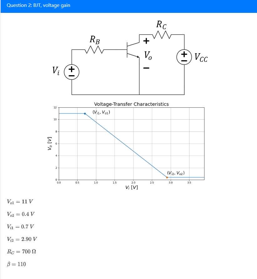
Solved Question 2 BJT, Voltage Gain (+Vcc VoltageTransfer
Unlocking the Mystery of VCC
1. VCC Explained
Ever stumbled upon the acronym "VCC" in electronics schematics or discussions and felt a slight shiver of confusion? Don't worry, you're not alone! VCC, at its core, stands for "Voltage Common Collector." However, in most modern contexts, especially when dealing with integrated circuits (ICs), microcontrollers, and digital logic circuits, it essentially signifies the positive supply voltage. Think of it as the lifeblood that keeps these electronic components ticking.
It's easy to get bogged down in the technical details, but the main takeaway is this: VCC provides the necessary electrical potential for the IC or component to operate correctly. Without the right VCC, your circuits simply won't function as intended. Its like trying to start your car with an empty gas tank — you might turn the key, but nothings going to happen.
Now, why "Common Collector" if it's mostly used as a positive supply? Historically, in bipolar junction transistor (BJT) circuits, the collector terminal was often connected to the positive voltage rail. While the specific circuit topology might not be relevant in many modern applications, the legacy of the term "VCC" has stuck. So, remember it as "Voltage at the Common Collector," or just "Positive Supply Voltage," and you'll be in good shape!
Essentially, VCC is the primary source of electrical energy for a circuit. Much like water flowing through pipes keeps a watermill turning, VCC provides the electrical current needed for transistors to switch, logic gates to process information, and microcontrollers to execute instructions. It is a fundamental element in the world of electronics, and understanding its purpose is crucial for anyone tinkering with circuits and devices.

Decoding the Voltage
2. Finding the Right Voltage
The voltage level associated with VCC isn't a one-size-fits-all deal. It varies depending on the specific component or circuit you're working with. Some ICs might require a VCC of 3.3 volts, while others may need 5 volts, 12 volts, or even higher. Supplying the wrong voltage can have dire consequences. Too little voltage and the circuit won't function reliably (or at all). Too much voltage, and you risk damaging or even destroying the component — think of it as accidentally plugging a phone charger into a high-voltage outlet!
So, how do you determine the correct VCC value? The answer lies in the component's datasheet. The datasheet is a document provided by the manufacturer that outlines the specifications and operating characteristics of the device. Within the datasheet, you'll find the recommended operating voltage (typically labeled as "VCC," "VDD," or something similar). It's essential to consult the datasheet before powering up any electronic component. Ignoring this step is like building a house without reading the blueprints — you're likely to encounter some pretty significant problems.
Sometimes, you might see a range of acceptable VCC values listed in the datasheet. This gives you a bit of wiggle room, but it's generally best to stick as close as possible to the recommended voltage. Operating the component outside the specified range can lead to unpredictable behavior, reduced performance, or even permanent damage. It is worth to remember that proper usage of VCC range will make component function with the specifications that is desired by the designer.
Always double-check the datasheet! It's the single most crucial source of information regarding a components operating parameters. Think of it as the ultimate instruction manual for your electronic components. By reading and understanding this information, you can avoid costly mistakes and ensure that your circuits function correctly and safely.
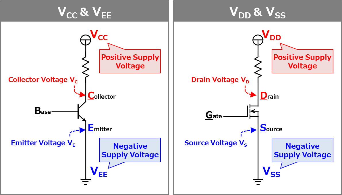
VCC vs. GND
3. Positive and Negative
VCC rarely works alone. It's typically paired with GND (Ground), which serves as the reference point for the voltage. GND is essentially the zero-volt point in your circuit. The voltage difference between VCC and GND is what drives the flow of current, allowing your circuit to perform its intended function. Imagine VCC and GND as the positive and negative terminals of a battery they need each other to complete the circuit.
While VCC provides the positive supply, GND acts as the return path for the current. The current flows from the VCC terminal, through the various components in your circuit, and then back to the GND terminal. This closed-loop path is essential for the circuit to operate. Without a proper GND connection, your circuit will be incomplete, and nothing will happen.
In some cases, you might encounter other voltage rails, such as VEE (negative supply voltage) or VDD (drain voltage). These are typically used in more complex circuits, but the fundamental principle remains the same: a voltage difference between two points is needed to drive the flow of current. Understanding VCC and GND is crucial, but it's also important to be aware of these other voltage rails when working with more intricate circuits.
Think of VCC and GND as two sides of the same coin — inseparable and equally important. While VCC provides the "push," GND provides the "pull," creating the necessary conditions for electrons to flow and your circuit to come to life. Ignoring the importance of either VCC or GND can lead to a non-functional or even damaged circuit. Always ensure that both are properly connected and that the voltage difference between them is within the specified limits.
Practical Considerations
4. Powering Up
Selecting the correct power supply for your VCC needs is critical for a stable and reliable system. The power supply needs to provide the correct voltage, as discussed earlier, but it also needs to be able to supply enough current to meet the demands of the circuit. If the power supply can't provide enough current, the voltage may drop, leading to unpredictable behavior or even damage to the components.
Consider using a regulated power supply to ensure a stable VCC. Regulated power supplies are designed to maintain a constant output voltage, even when the input voltage or the load current changes. This is important because fluctuations in the VCC can cause problems with circuit operation. Imagine a car engine that randomly speeds up and slows down — it would be difficult to control! A regulated power supply provides a steady and predictable source of power, making your circuit much more reliable.
When choosing a power supply, pay attention to its specifications, including the output voltage, output current, and regulation. Make sure that the power supply is rated to handle the maximum current draw of your circuit. It's generally a good idea to choose a power supply with a slightly higher current rating than you need, to provide some headroom and prevent the power supply from overheating. It's like having extra storage space on your computer — it's better to have more than you need than to run out.
Don't skimp on the quality of the power supply. A cheap and unreliable power supply can introduce noise and instability into your circuit, leading to problems. Investing in a good quality power supply is a worthwhile investment that can save you headaches down the road. Remember, a reliable power supply is the foundation of a stable and dependable circuit.
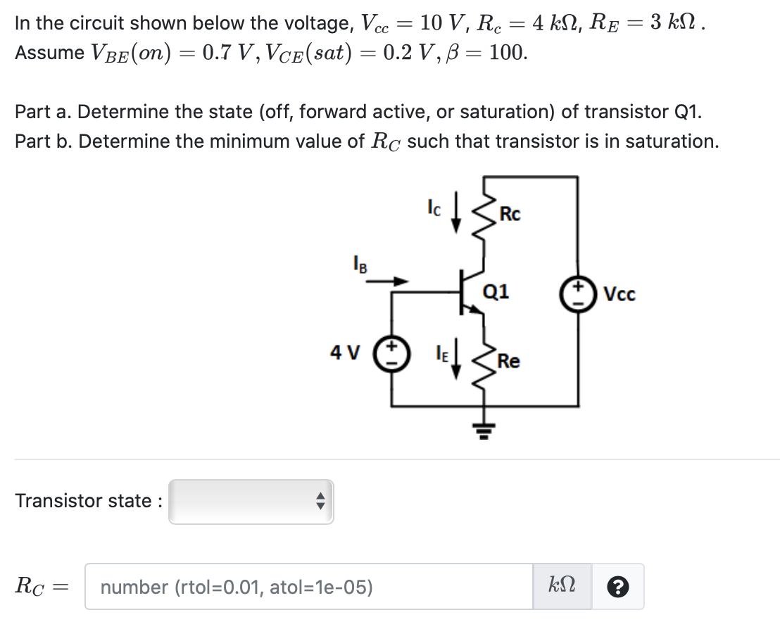
Solved In The Circuit Shown Below Voltage, Vcc 10 V,
Troubleshooting VCC Issues
5. Debugging Dilemmas
Even with careful planning, VCC-related issues can still arise. If your circuit isn't working as expected, the first thing you should check is the VCC voltage. Use a multimeter to measure the voltage at the VCC pin of the IC or component. Is it within the specified range? If not, there's a problem with your power supply or the connection to the power supply. Double-check the wiring and make sure that the power supply is providing the correct voltage.
If the VCC voltage is correct, the next thing to check is the GND connection. A poor or loose GND connection can cause all sorts of problems. Use a multimeter to check the continuity between the GND pin of the IC and the GND terminal of the power supply. If there's no continuity, there's a problem with the GND connection. A good GND connection will ensure that current has a reliable return path, which is crucial for proper circuit operation.
Sometimes, VCC problems can be caused by shorts or overloads in the circuit. A short circuit is a low-resistance path that allows excessive current to flow, potentially damaging components. An overload occurs when the circuit draws more current than the power supply can provide. If you suspect a short circuit or overload, disconnect the power supply and carefully inspect the circuit for any obvious shorts or damaged components. Then, use a multimeter to check the resistance between VCC and GND. A low resistance indicates a short circuit. Addressing short circuits or overloads is necessary for circuit stability and preventing damage.
Isolate the problem. Disconnect sections of the circuit to see if the VCC voltage returns to normal. This can help you narrow down the source of the problem. It's like trying to find a leak in a pipe — you start by closing off sections of the pipe until you find the location of the leak. By systematically isolating parts of the circuit, you can eventually pinpoint the cause of the VCC issue and get your circuit back up and running.
FAQ
6. Frequently Asked Questions
Q: What's the difference between VCC and VDD?
A: Often, not much! VCC is commonly used for bipolar junction transistor (BJT) circuits, while VDD is often used for MOSFET circuits. However, in many contexts, they're used interchangeably to refer to the positive supply voltage. Always check the datasheet to be sure.
Q: Can I use a higher VCC than the datasheet specifies?
A: Definitely not! Exceeding the maximum VCC rating can damage or destroy the component. Stick to the recommended voltage range specified in the datasheet.
Q: What happens if my VCC voltage is too low?
A: The circuit may not function correctly or at all. Performance can be erratic, and digital logic may produce incorrect outputs. Increasing to the proper VCC is usually necessary.
Q: My circuit is still not working, even with the correct VCC! What should I do?
A: Double-check all your connections, verify the functionality of other components, and consult the datasheet for any specific troubleshooting tips. There could be an issue besides voltage.